
Main Parts, ILF ( auto flush filter)
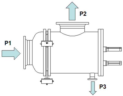
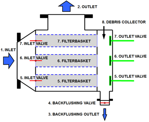 1. Main inlet
2. Main outlet
3. Back flushing outlet
4. Back flushing valve
5. Filterbasket, inlet valve and outlet valve
6. Filterbasket, inlet valve and outlet valve
7. Filterbasket, inlet valve and outlet valve
8. Debris collector
Operation, ILF
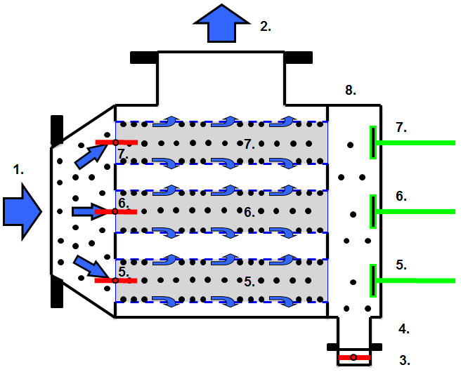
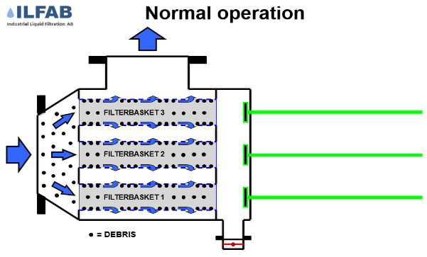
Normal Operation
The raw liquid enters the filter baskets (5, 6, 7) through the main inlet (1). The inlet and outlet valves (5, 6, 7) are all in open positions. The flushing valve (4) is closed. The liquid is being filtrated when it passes through the filter baskets prior to being discharged at the main outlet (2). The debris is collected inside the baskets and in the debris collector (8)
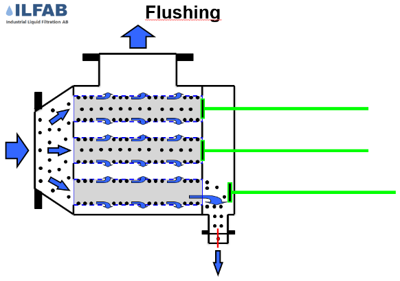
Regeneration Flushing
Flushing takes place either in one or two steps depending on actual conditions of the water .

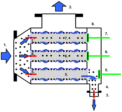
1) Pre-flushing, all baskets
The flushing valve opens, thereby reducing the pressure drop and increasing the flow velocity and total flow through the filter. The filter basket’s inlet and outlet valves are in open positions. Any collected debris in the baskets and in the debris collector is flushed out through the flushing outlet due to the pressure and flow conditions inside the filter. Pre-flushing is recommended only if conditions are bad.
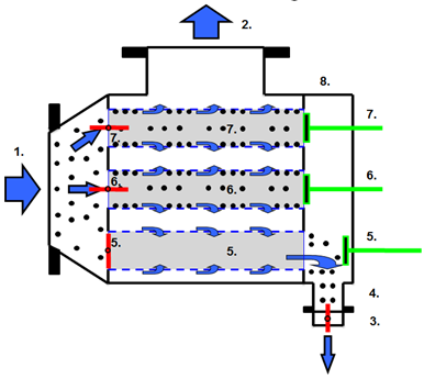
2) Flushing, actual basket
The flushing valve remains open. The filter basket’s (6, 7) outlet valves (6, 7) are in closed position. The outlet valve (5) at the filter basket (5) is still in open position. The flow is now diverted and forced to pass through the filter basket (5). The velocity inside the filter basket (5) is now increasing also due to the differential pressure, and the basket (5) is being well flushed clean of all remaining debris collected inside the filter basket.
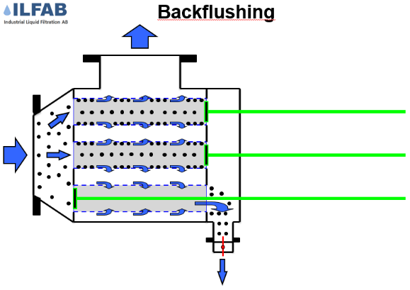
Regeneration back flushing
The back flushing valve remains open and the inlet valve (5) of the filter basket (5) is in closed position. The outlet valves of the filter baskets (6, 7) are kept in closed position. A certain portion of the filtrated liquid back flushes 100% of the filter basket (5). Dislodged remnants are washed out through the flushing valve. The entire cleaning operation takes place without interrupting the outlet flow.
Technical information, ILF.
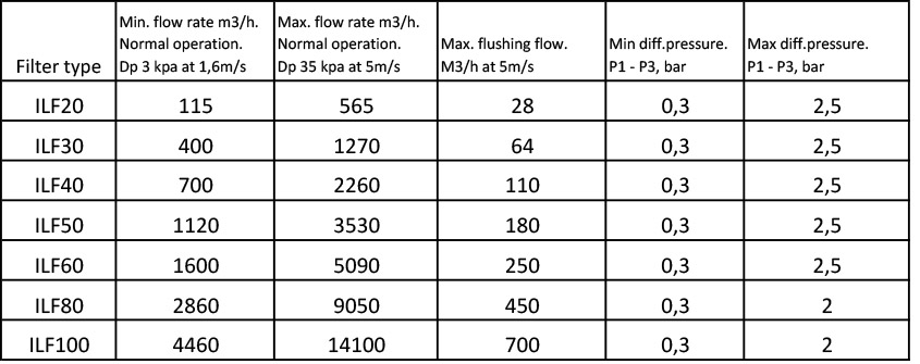
Designed flow capacities: from 180m3/h up to 14000m3/h.
Available materials: stainless steel EN 1.4436/ ASTM316, ASTM S31254 SMO or Carbon steel P265 GH/ ASME 516 Gr.60, internally lined with Glass Flake Polyester.
Inlet / outlet connections: DN200/8″, DN300/12”*, DN400/16”, DN500/20”, DN600/24”, DN800/32”, DN1000/40”.
Connections standards: EN1092-1, PN10, ASME B16.5, Class 150.
Mesh size: From 50 microns to 5mm.
Operation: Pneumatic or electric.
Design code: EN13445 and ASME VIII div.1.
Design pressure: 10 barg, 150psi
Design temperature: 65 deg.C, 149 deg.F
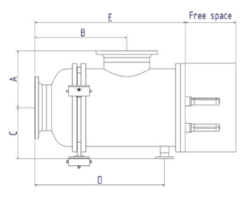
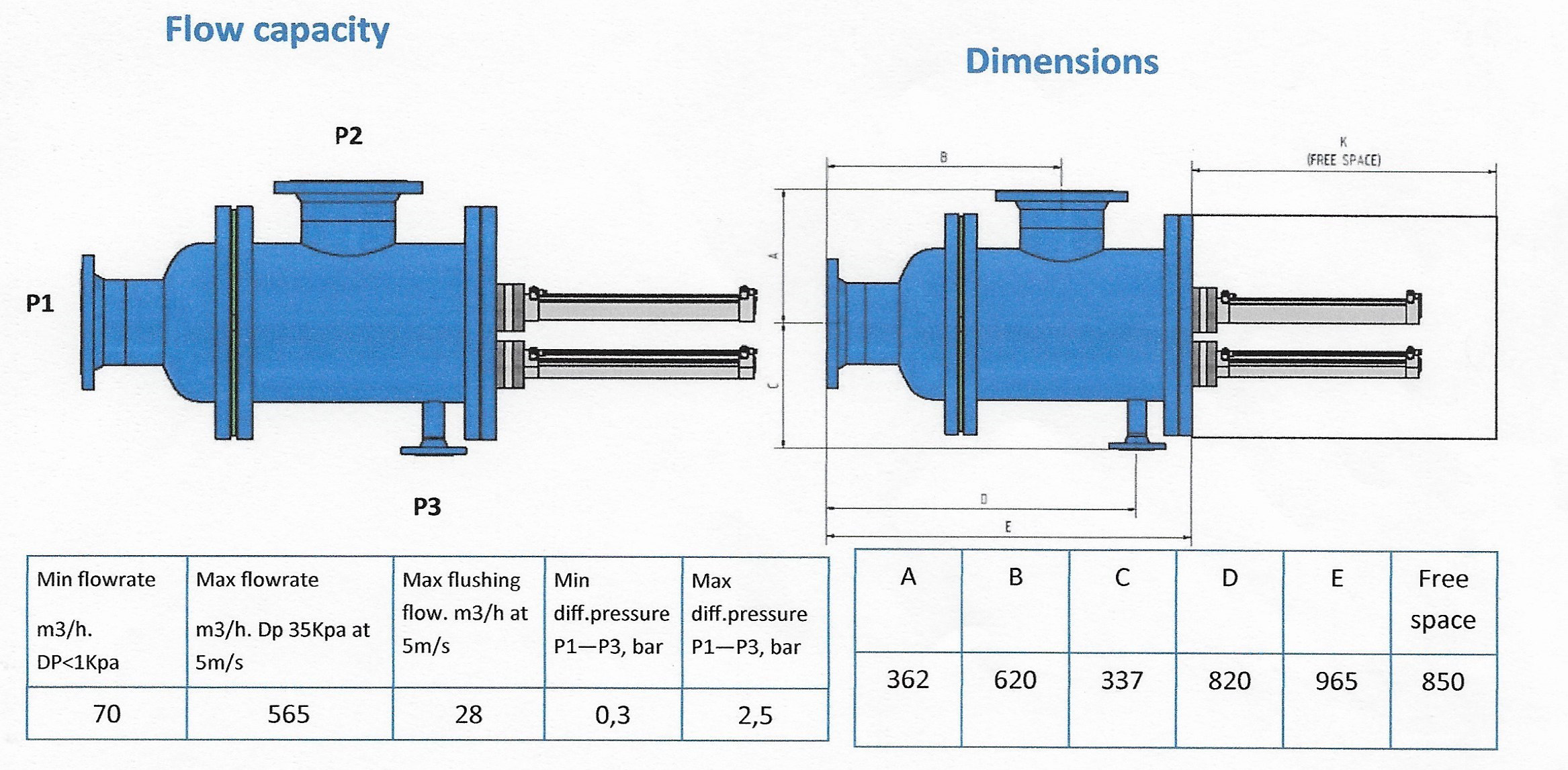
ILF Dimensions

Recommended flowrates
ILF20L – Technical Information
ILF20L a corrosion safe filter with bolt blackflushing and mechanical cleaning of the filter baskets.
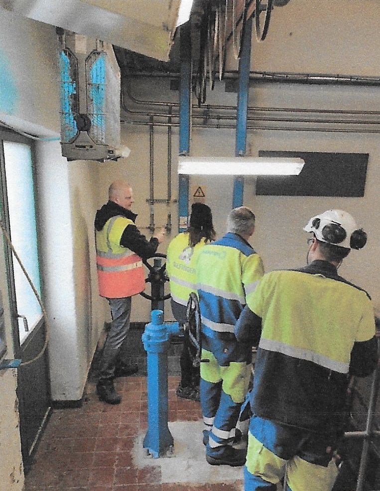
A team from ILFCO and Outokumpu are looking for a suitable installation place for an ILF filter at Outokumpu Avesta Steel Work.
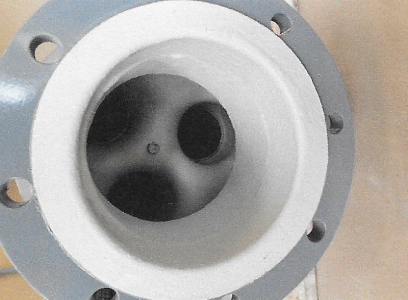
ILF Filters are lined with glass flake polyester that guarantees a corrosion-proof design.
ILF20 L Function
Normal Operation
The raw liquid enters the filter baskets through the main inlet (1). The piston valves (5, 6, 7) are all in open positions. The flushing valve (4) is closed. The liquid is filtrated when it passes through the filter baskets prior to being discharged at the main outlet (2). The debris is collected in the debris collector (8)
Regeneration flushing
The flushing valve (4)remains open. The filter baskets (6, 7) piston valves (6, 7) are in closed position. The piston valve (5) at the filter basket (5) is still in open position. The flow is now diverted and forced to pass through the filter basket (5). The velocity inside the filter basket (5) is now increasing also due to the differential pressure, and the basket (5) is being well flushed clean of all remaining debris collected inside the filter basket.
Regeneration Back flushing
The flushing (4) valve remains open and the piston valve (5) of the filter basket (5) is in closed position. The piston valves of the filter baskets (6, 7) are kept in closed position. A certain portion of the filtrated liquid back flushes 100% of the filter basket (5). Dislodged remnants are washed out through the flushing outlet (3). The entire cleaning operation takes place without interrupting the outlet flow.
Control panel with a touch panel
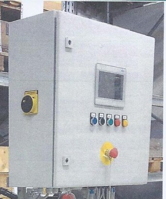 Control with PLC and touch panel for one filter.
Alternative configurations are available for controlling multiple filters.
Protection class: IP65/ NEMA4,
Power supply 100 – 250VAC, single phase, 50 – 60 Hz.
The panel is supplied with alarms for wrong operations and high differential pressure.
Remote control and high protection classes on request.